Rtd Standard Wiring Diagram

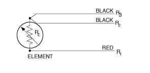
Rtd Wiring And Colour Codes Southern Temperature Sensors Ltd
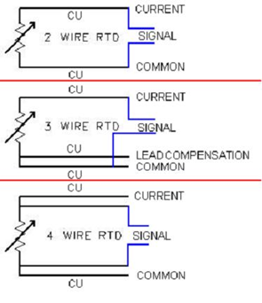
2 3 And 4 Wire Rtds What Is The Difference
Rtd Wiring Diagrams
Http Www Jumousa Com En Us Support Faq Temperature Measurement T1 Q3 Html

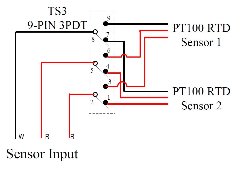
Pt100 Rtd Colour Codes Iec 60751

Kk 9411 Wire Color Code Also Wiring Diagram On Tc Rtd Wiring

Rtd wiring overview created date.
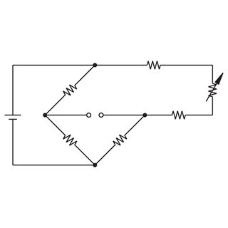
Rtd standard wiring diagram. It reveals the parts of the circuit as simplified forms and also the power and also signal links between the devices. A wiring diagram is a streamlined standard photographic depiction of an electrical circuit. Shown is a 2 wire rtd connected to a typical wheatstone bridge circuit. Generally speaking field devices have inputs for 3 wire sensors to.
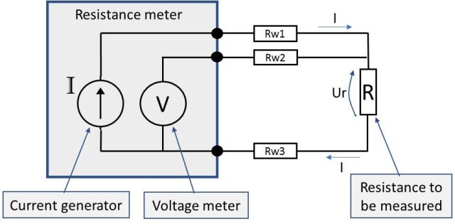
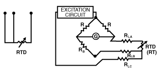
Eo is the output voltage. And rt is the rtd. L1 and l3 carry the measuring current while l2 acts only as a potential lead. R1 r2 and r3 are fixed resistors.
Normally a 2 wire rtd will lose accuracy due to the resistance in the cable which can be thousands of feet long. The 3 wire rtd uses 1 additional wire and the 4 wire rtd uses 2 additional wires to compensate for the wire resistance. Es is the supply voltage. Wellborn assortment of rtd pt100 3 wire wiring diagram.
In this uncompensated circuit lead resistance l1 and l2 add directly to rt. December 12 2018 by larry a. No current flows through it while the bridge is in balance since l1 and l3 are in separate arms of the bridge resistance is canceled. 3 wire rtd wiring diagram in this circuit there are three leads coming from the rtd instead of two.
Wellborn collection of 3 wire rtd wiring diagram. It shows the components of the circuit as streamlined shapes and also the power and also signal links between the gadgets. Wiring there are 2 wiring methods for the rtd module and pt100 temperature sensors two wire and three wire connections.
Wilkerson Instrument Company Inc Blog Rtd
Tube Wire General Purpose Rtd Thermocouple Online Com

What Is An Rtd Rtd Types Uses And More By Jms Southeast
Resistance Measurement 2 3 Or 4 Wire Connection How Does It
Rtd Elements And Sensors Introduction And Tables
Chapter 7 Temperature Measurement Rtd Measurement Circuits
Connecting 2 3 And 4 Wire Rtds To My Data Acquisition Card

Measure Temperature Using A Rtd Mydaq And Labview Ni Community
Temperature Pt 2 Hardware Craig Lyn Design Studio
Temperature Sensors Auber Instruments Inc Temperature Control
Definitions For Rtds

4 Wire Rtd Evolution Sensors And Controls

Rtd Temperature Measurement With Usb Data Acquisition Hardware
