Motorola Voltage Regulator Wiring Diagram

A tractor s regulator takes the voltage provided by the battery manages it.
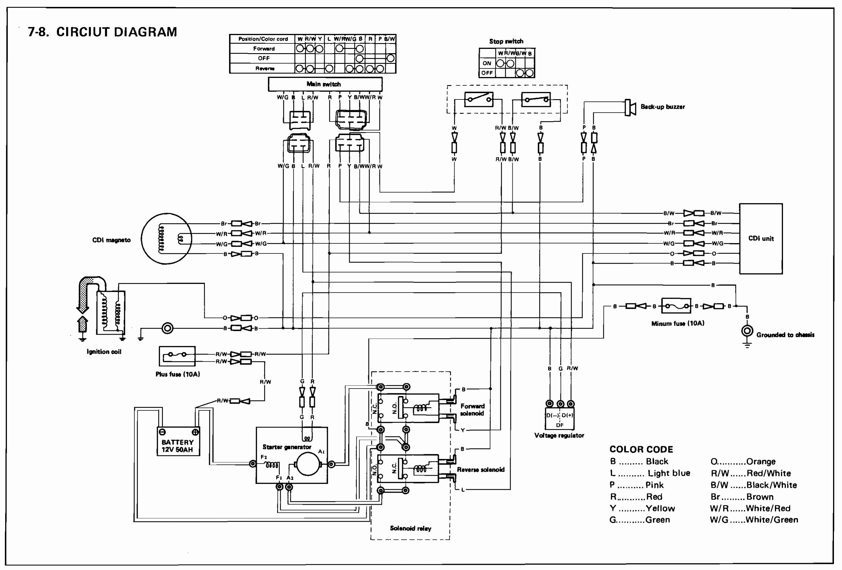
Motorola voltage regulator wiring diagram. 1969 chevy truck alternator and regulator wiring wiring volvo motorola alternator external regulator wiring diagram. The reason is the regulator body is an integral part of the ignition protection package required by the uscg. A wiring diagram is a simplified conventional pictorial depiction of an electrical circuit. Variety of motorola voltage regulator wiring diagram.
Each part ought to be set and connected with different parts in specific manner. If you decide to use a remote regulator the original must remain in place even if not connected. Wiring diagrams include two things. Symbols that represent the constituents inside circuit and lines that represent the.
Fluctuation in voltage can harm these electrical mechanisms. Motorola units are similar in size to a delco alternator of the same era and also use an external transistorized voltage regulator. Motorola voltage regulator wiring diagram what s wiring diagram. A wiring diagram is a kind of schematic which uses abstract pictorial symbols to demonstrate each of the interconnections of components in a system.
Six volt generators and 12 volt alternators require current at voltages. This pertains to the standard motorola 35 amp alternator originally supplied on the atomic 4. Leece neville motorola 8lha series alternators replaces regulator motorola 8rg2101a prestolite 105 329 m5563 voltage regulator 12 volt a circuit low side drive regulator ac ac fld b b terminals 14 3 vset for motorola alternators. If not the structure won t function as it should be.
It reveals the components of the circuit as simplified shapes as well as the power and signal connections between the tools. M5329a voltage regulator 12 volt a circuit 14 2 volt set point for. A voltage regulator takes current from a battery with oscillating voltage and puts out constant voltage.


