Motor Starter Wiring Diagram Aquastat

New Wiring Diagram For Ge Electric Motor Diagram Diagramsample

Doityourself Com Community Forums Hot Water System

An Aquastat Wiring Wiring Diagram
Aquastats Diagnosis Repair Setting Wiring Heating System

Heating System Diagrams Google Search With Images Radiant
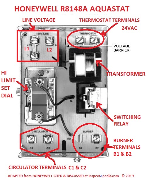
Honeywell Aquastat L8148e Wiring Diagram Wiring Diagram

Typically an induction motor will run by a.
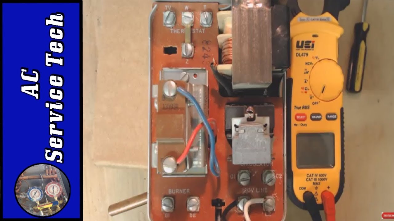
Motor starter wiring diagram aquastat. 3 and 4 show typical wiring diagrams of aquastat controllers used in heating systems. How to wire a motor starter number. Honeywell l8148a e j aquastat relay series manual controllers pdf 2001 product data installation operation manual including l8148 wiring diagrams. In north america an induction motor will typically operate at 230v or 460v 3 phase 60 hz and has a control voltage of 115 vac or 24 vdc.
The case has a knockout for 1 2 in. Wiring diagrams show the connections to the controller. Wiring diagrams sometimes called main or construction diagrams show the actual connection points for the wires to the components and terminals of the controller. It reveals the parts of the circuit as simplified shapes and the power and signal links between the gadgets.
Internal view of. A wiring diagram is a simplified traditional photographic representation of an electric circuit. The l8148a e j aquastatæ relays are immersion type controllers for use with forced hydronic heating systems. Basic wiring for motor control technical data.
Original a motor starter is a combination of devices to allow an induction motor to start run and stop according to commands by an operator or a controller. A motor starter is a combination of devices used to start run and stop an ac induction motor based on commands from an operator or a controller. Collection of single phase motor starter wiring diagram.

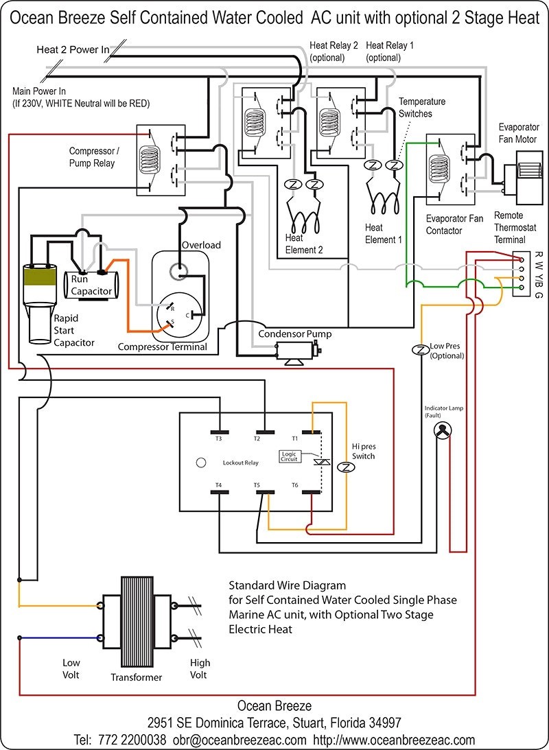
How To Wire An Air Conditioner For Control 5 Wires Easy

New Wiring Diagram For Solid Fuel Central Heating System

Furnace Thermostat Wiring Diagram On A C Thermostat Wiring Diagram
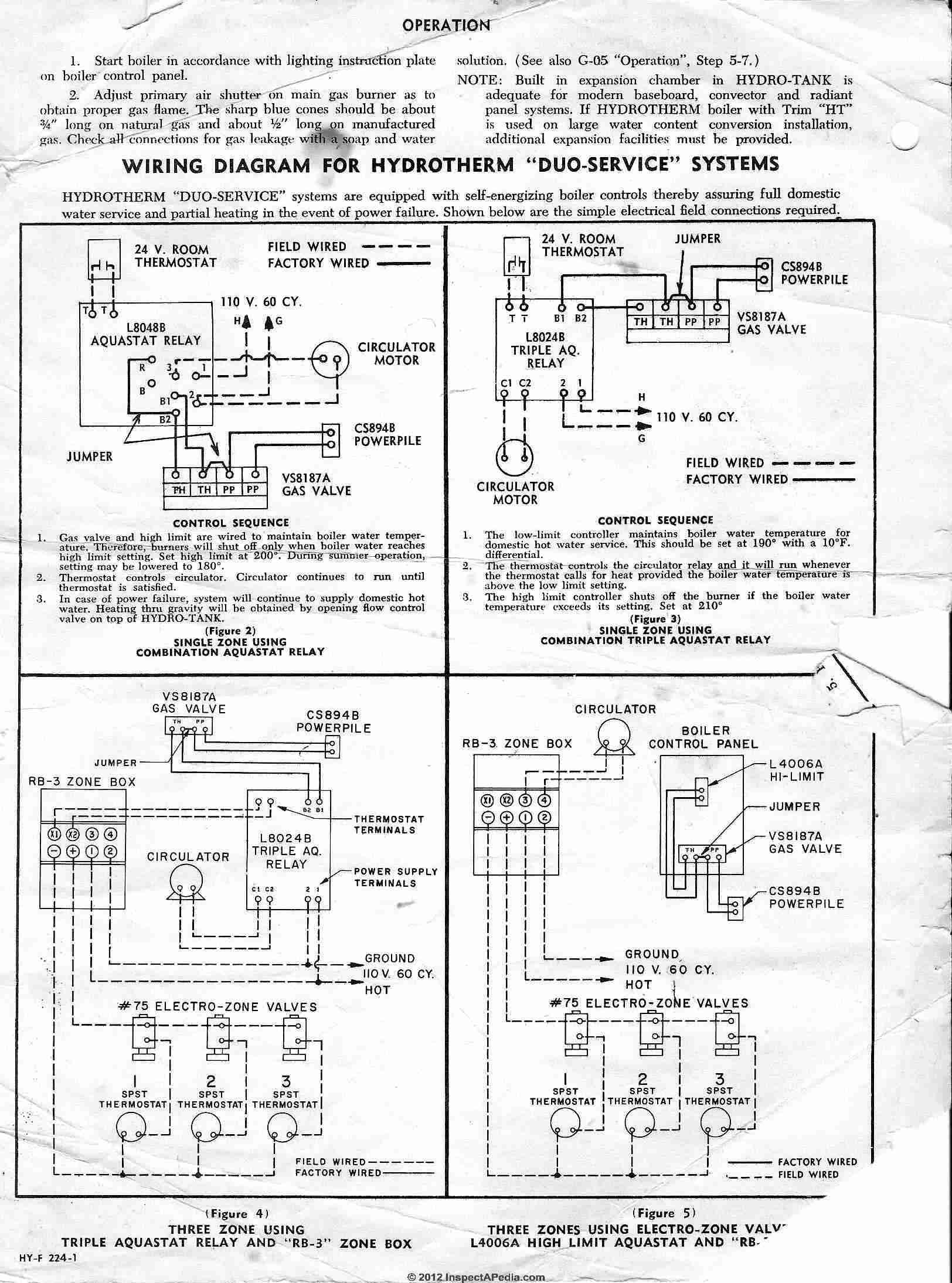
Heating Boiler Aquastat Control Diagnosis Troubleshooting Repair

Bx 2348 Honeywell Relay R8222d1014 Wiring Diagram Free Diagram
New Aquastat L8148e No Voltage To Burner Doityourself Com
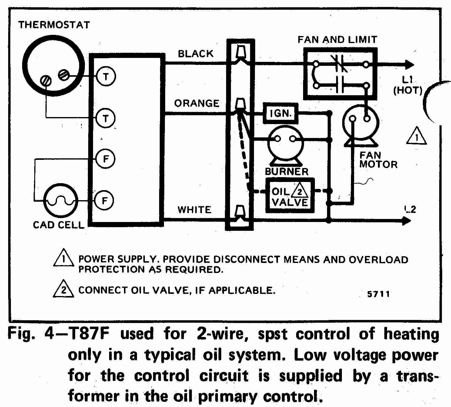
How Wire A Honeywell Room Thermostat Honeywell Thermostat Wiring
Boiler Aquastat Relay Troubleshooting And Control Wiring Youtube
Honeywell Aquastat L8148e Wiring Diagram General Wiring Diagram
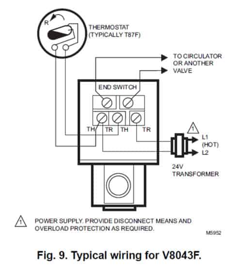
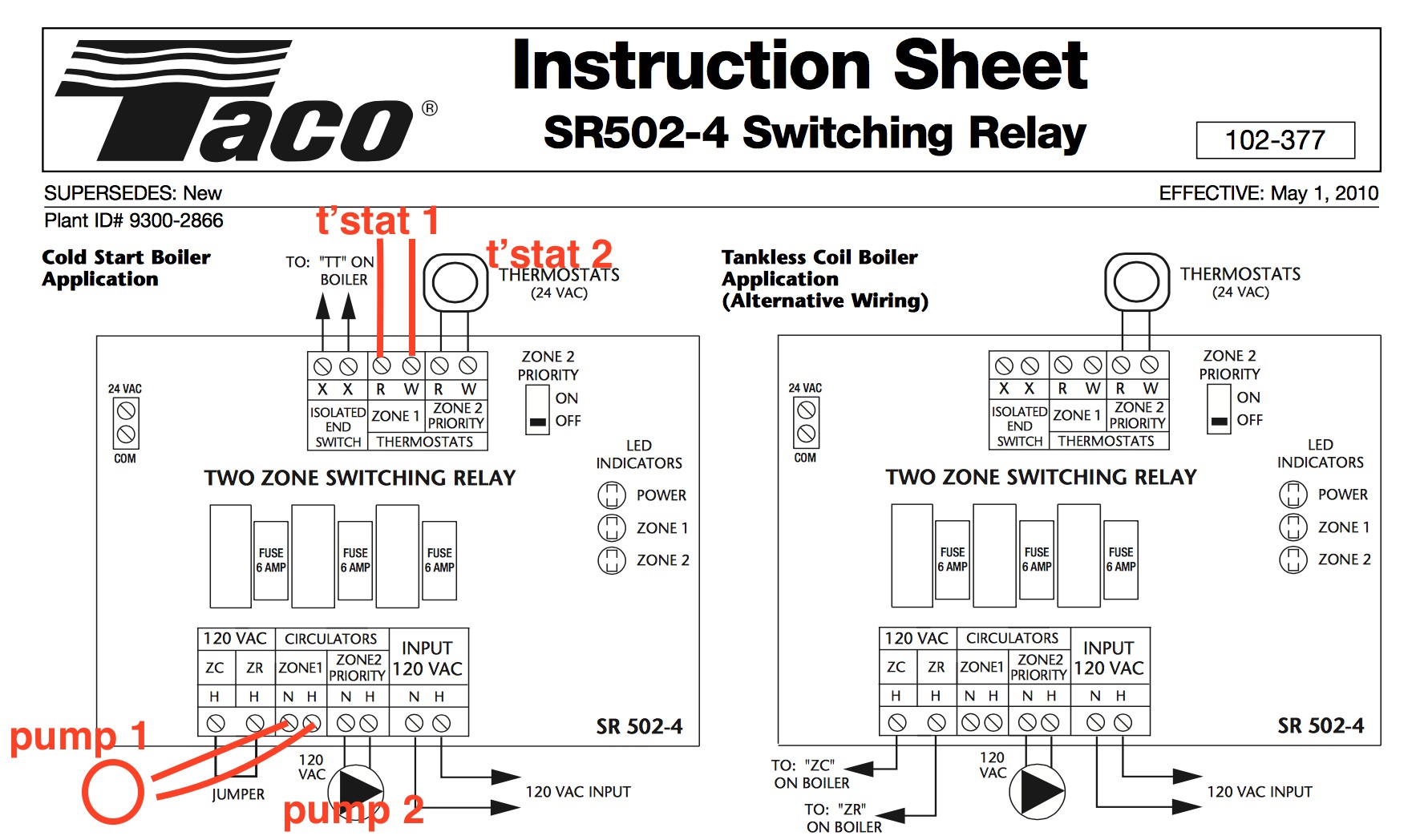
Hot Water Boiler Piping Zone Valves And Wiring Diagrams

L8124 Wiring Diagram Aquastat Wiring Diagram

Blueprint Abbreviations Fernandinirios Blueprints

Inspirational Autodata Wiring Diagram Symbols Diagrams
