Boss V Plow Valve Body Wiring Diagram

Hyd01602 valve manifold layout.
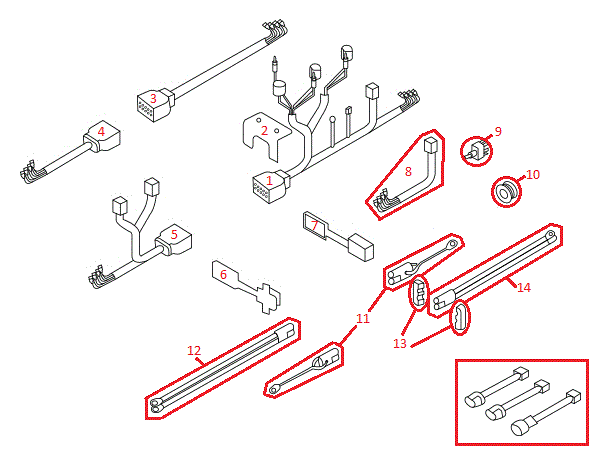
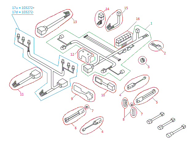
Boss v plow valve body wiring diagram. Boss snowplow a division of m j. A wiring diagram normally gives info regarding the relative placement and plan of gadgets as well as terminals on the gadgets to assist in structure or servicing the device. Snowplow assembly procedure 4 snowplow assembly procedure note. 31 valve manifold rt3 v blade w smarthitch hyd07044 1 31a valve lift angle hyd01637 6 31b valve smarthitch attach hyd07047 1 31c valve flow control hyd07048 1 31d valve relief v blade 2800psi hyd01639 2 31e valve check hyd01640 4 31f valve coil hyd01638 7 31g valve ground strap hyd01647 7 31h coil nut hyd07059 6.
Collection of boss v plow wiring diagram. Rapid tach il wiring schematic. Defective lift valve coil screen cartridge on valve body plugged b c. A wiring diagram is a simplified standard photographic depiction of an electrical circuit.
Talk now with boss. Part numbers and illustrations may vary. It shows the components of the circuit as simplified shapes and the facility and signal connections amid the devices. Intercon truck equipment 1200 pauls lane joppa md 21085 tel.
Power v hydraulic switch assembly wiring diagram. Begin the assembly procedure by cutting down each. It shows the elements of the circuit as streamlined forms as well as the power and signal links between the devices.


