Boss Rt3 V Plow Wiring Diagram
Boss Rt3 Snow Wiring Diagram Diagram Base Website Wiring Diagram

Boss Part Msc13060 Utv Vplow Center Hinge Pin Kit You Can

Snowdogg Part 16160302 Gen2 Truckside Controller Harness

Mc 9706 Boss Rt3 Straight Blade Wiring Diagram Wiring Diagram

Boss V Plow Valve Body Wiring Diagram Wiring Diagram
Wiring Diagram For A Boss V Plow Wiring Diagram

Disconnect the left and right headlight connector plugs from the left and right vehicle headlights.
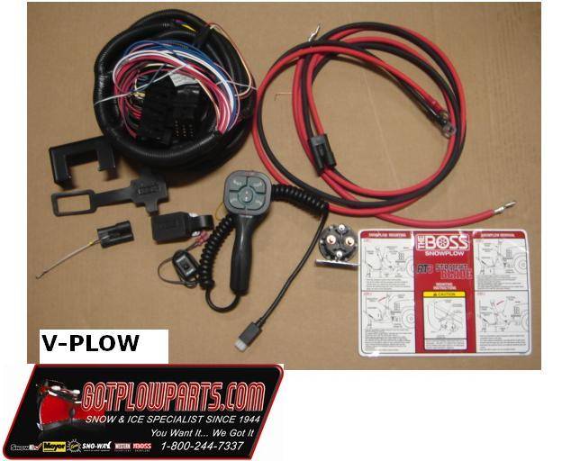
Boss rt3 v plow wiring diagram. Part numbers and illustrations may vary. Begin the assembly procedure by cutting down each corner of the plow box so that each wall of the box will lie flat on the floor. Boss rt3 wiring diagram wiring diagram is a simplified welcome pictorial representation of an electrical circuit. It shows the components of the circuit as simplified shapes and the gift and signal links together with the devices.
12 rt3 power v with smarthitch assembly drawing figure 7. To keep your boss plow in top shape take a few minutes to study this manual. Connect both sealed beam connectors a from the headlight adapter kit into the vehicle headlights. It will show you how to use and service the boss familiarize you with all of its parts and give you helpful tips on plowing snow.
The boss snowplow has been carefully designed and built for years of carefree. This manual is used for the installation of all v plows. Rt3 power v blade with smarthitch wiring procedure note. 6 8 2001 7 50 27 pm.
If you have further questions your local boss dealer is the person to. Rt3 wiring diagram rt3 wiring diagram. The box can be used as a. All instructions below are illustrated in figure 10.
Rt3 smarthitch 2 wiring diagram 13 pin rt3 smarthitch 2 wiring diagram 13 pin.
Truck Side Wiring Harness Boss Diagram Base Website Harness Boss

Rt3 Boss Plow Wiring Diagram Wiring Diagram

How Hard Could It Be Installing The Wiring Harness For A Boss
Boss Wiring Harness Diagram Wiring Diagram
Boss Plow Wiring Diagram Dodge Wiring Diagram

Wiring Diagram Boss V Plow 1996 Chevy Wiring Diagram

Beigu Multifunction Car Ice Breaker Snow Brush Snow Removal Tools

Boss Snow Plow Headlight Wiring Diagram Wiring Diagram
Boss Snow Plow Wiring Diagram Wiring Diagram

Vantiyaus Ice Scraper2 Pack Snow Remover With Squeegee Strip For

Ship From Usa 10 Pk Shear Pins W Bolts Fits Mtd 7100890 7100890a

Snow Moover 55 Extendable And Ice Scraper With Foam Grip Auto Snow
Rt2 Boss Smart Hitch Wiring Schematic Wiring Diagram
