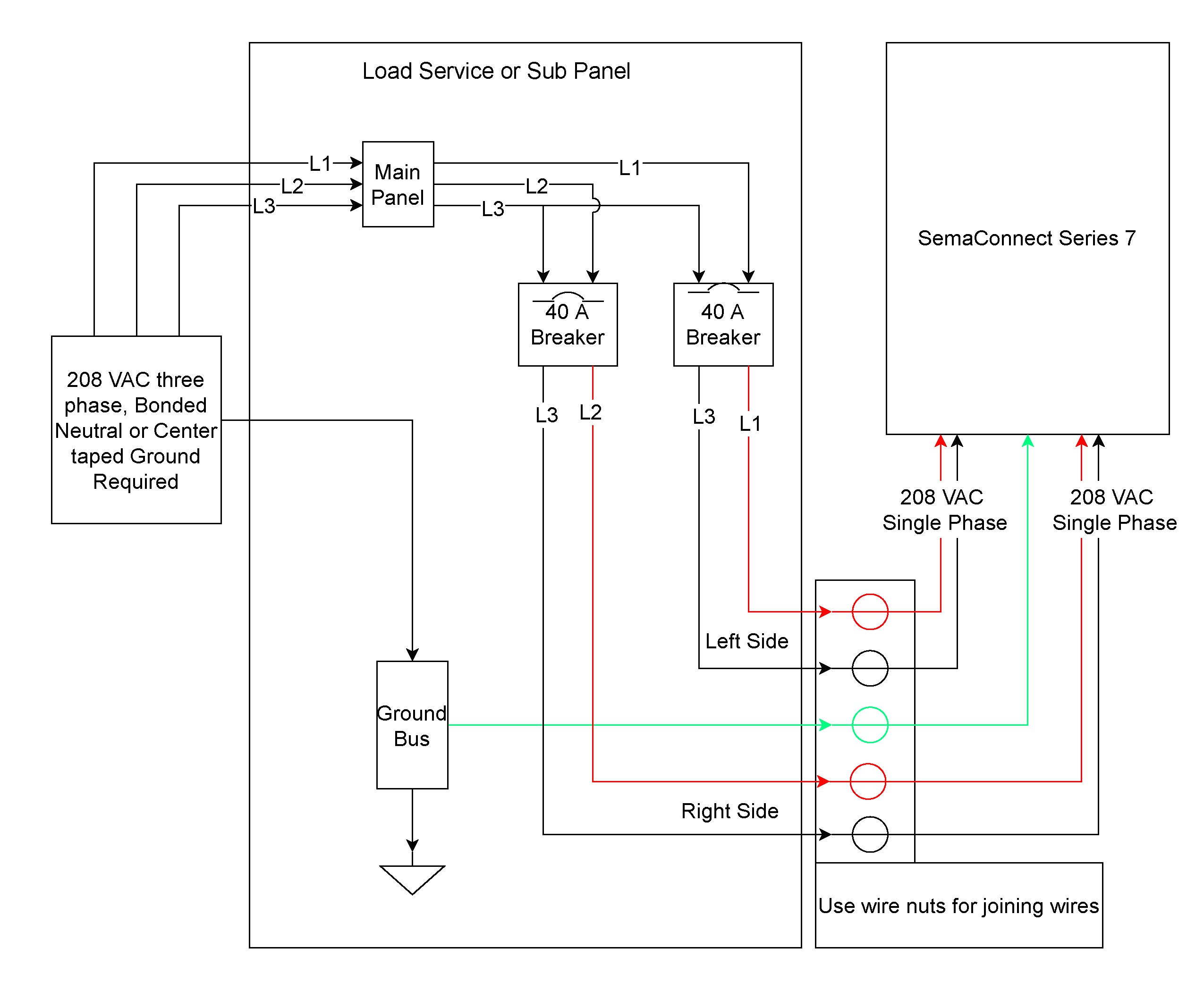
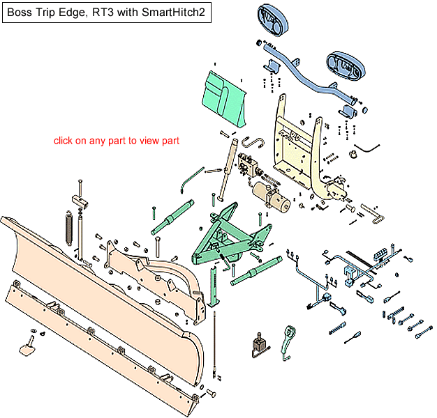
Boss Rt3 Snow Plow Wiring Diagram

Driveways plow shoes can be raised up to increase cutting edge contact on the plowed surface.
Boss rt3 snow plow wiring diagram. Rt3 smarthitch 2 wiring diagram 13 pin rt3 smarthitch 2 wiring diagram 13 pin. Rt3 wiring diagram rt3 wiring diagram. When plowing on a solid level area parking lots roads and driveways plow shoes can be raised up to increase cutting edge contact on the plowed surface. 10 rt3 straight blade wiring schematic figure 6.
When plowing dirt gravel or grass plow shoes should be lowered below the cutting edge surface to prevent the plow from digging into the plowed surface. Driven to be the best stb03278 12 boss products a division of northern star industries inc. A wiring diagram usually gives counsel virtually the relative aim and deal of devices and terminals on the devices to encourage in building or servicing the device. 6 8 2001 7 50 27 pm.
Wiring diagram smartlight2 wiring schematic smartlight2 control plug pin functions. 11 rt3 power v blade with smarthitch wiring schematic figure 6. When plowing dirt gravel or grass plow shoes should be lowered below the cutting edge surface to prevent the plow from digging into the plowed surface. Rt3 wiring schematic g10004.
Puts snow in its place a division of m j. The plow is mounted on the vehicle. Push frame attachment g10060 4. If you have further questions your local boss plow dealer is the person to talk to.
Rt3 straight blade wiring diagram figure 5. 11 rt3 straight blade assembly drawing. Rt3 wiring diagram g10002 straight blade manifold hyd07045 see figure 4. Your boss plow is designed for heavy duty rugged service with minimal maintenance.
Attach push frame attachment bar 3 to plow. Box 788 iron mountain mi 49801 0788 rt3 straight blade with owner s manual and.


