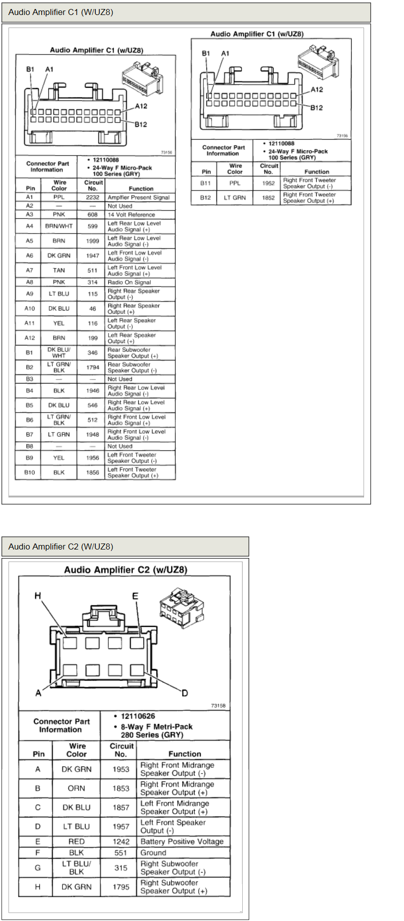
Bose Speaker Wiring Diagram

Connect each speaker matching the red wire positive to the red terminal and the black wire negative to the black terminal.
Bose speaker wiring diagram. Assortment of bose amp wiring diagram. What is speaker impedance. It shows the components of the circuit as simplified shapes and the capability and signal links along with the devices. Driver replacement 4 1 connect the speaker wires to the new driver.
It shows the components of the circuit as simplified shapes and also the power as well as signal connections in between the devices. How you go about connecting the bose 901 series equalizer to your stereo system varies slightly depending on whether you intend to use it in a two speaker or surround sound setup. A wiring diagram is a streamlined traditional photographic representation of an electrical circuit. The ohms rating speakers much like other electromechanical devices all have an electrical resistance to the flow of electrical current much like a standard resistor a light bulb or many common items you re familiar with.
Speaker basics and speaker wiring explained 1. 0 collapse. Collection of bose amp wiring diagram. Staple location figure 3.
The speaker wire as close to the driver terminals as possible. 4 2 place the new driver and gasket into the cabinet and secure it in place. A wiring diagram is a simplified standard pictorial depiction of an electrical circuit. 4 3 perform procedure 2.
It shows the parts of the circuit as streamlined forms as well as the power and signal connections between the tools. Bose 321 speaker wire diagram wiring diagram is a simplified normal pictorial representation of an electrical circuit. Ignore the red black speaker wires and the terminal screws in the image those are used to adapt standard speaker wire for use with the connector for a bose speaker. You ve purchased a bose 901 equalizer by itself or as a part of a bose 901 speaker system and now it s time to set it up.
Refer to figure 4 for the wire dia gram. Surround speaker cables have orange plugs at one end with l and r molded into the plug housing.


